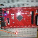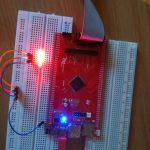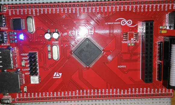
در این پست برنامه کار با واحد اینتراپت میکروکنترلر stm32f407 را برای شما گذاشته ایم. طریقه کار برنامه به این صورت می باشد که یک عدد LED به پایه شماره PE0 متصل کرده ایم و رقفه خارجی نیز روی پایه PE3 قرار داده شده است با تحریک پایه وقفه که روی لبه بالا رونده تنظیم شده است برای بار اول LED روشن می شود و اگر دوباره تحریک صورت بگیرد LED خاموش می شود .میکروکنترلر stm32f407 محصول شرکت st بوده و از فرکانس 168مگاهرتز بهره می برد.این میکروکنترلر دارای حافظه فلش به ظرفیت 1 مگابایت می باشد و در زیر خصوصیات آن آورده شده است.
Key Features
- Core: ARM® 32-bit Cortex® -M4 CPU with FPU, Adaptive real-time accelerator (ART Accelerator™) allowing 0-wait state execution from Flash memory, frequency up to 168 MHz, memory protection unit, 210 DMIPS/1.25 DMIPS/MHz (Dhrystone 2.1), and DSP instructions
- Memories
- Up to 1 Mbyte of Flash memory
- Up to 192+4 Kbytes of SRAM including 64-Kbyte of CCM (core coupled memory) data RAM
- Flexible static memory controller supporting Compact Flash, SRAM, PSRAM, NOR and NAND memories
- LCD parallel interface, 8080/6800 modes
- Clock, reset and supply management
- 1.8 V to 3.6 V application supply and I/Os
- POR, PDR, PVD and BOR
- 4-to-26 MHz crystal oscillator
- Internal 16 MHz factory-trimmed RC (1% accuracy)
- 32 kHz oscillator for RTC with calibration
- Internal 32 kHz RC with calibration
- Sleep, Stop and Standby modes
- VBAT supply for RTC, 20×32 bit backup registers + optional 4 KB backup SRAM
- 3×12-bit, 2.4 MSPS A/D converters: up to 24 channels and 7.2 MSPS in triple interleaved mode
- 2×12-bit D/A converters
- General-purpose DMA: 16-stream DMA controller with FIFOs and burst support
- Up to 17 timers: up to twelve 16-bit and two 32-bit timers up to 168 MHz, each with up to 4 IC/OC/PWM or pulse counter and quadrature (incremental) encoder input
- Debug mode
- Serial wire debug (SWD) & JTAG interfaces
- Cortex-M4 Embedded Trace Macrocell™
- Up to 140 I/O ports with interrupt capability
- Up to 136 fast I/Os up to 84 MHz
- Up to 138 5 V-tolerant I/Os
- Up to 15 communication interfaces
- Up to 3 × I2 C interfaces (SMBus/PMBus)
- Up to 4 USARTs/2 UARTs (10.5 Mbit/s, ISO 7816 interface, LIN, IrDA, modem control)
- Up to 3 SPIs (42 Mbits/s), 2 with muxed full-duplex I2S to achieve audio class accuracy via internal audio PLL or external clock
- 2 × CAN interfaces (2.0B Active)
- SDIO interface
- Advanced connectivity
- USB 2.0 full-speed device/host/OTG controller with on-chip PHY
- USB 2.0 high-speed/full-speed device/host/OTG controller with dedicated DMA, on-chip full-speed PHY and ULPI
- 10/100 Ethernet MAC with dedicated DMA: supports IEEE 1588v2 hardware, MII/RMII
- 8- to 14-bit parallel camera interface up to 54 Mbytes/s
- True random number generator
- CRC calculation unit
- 96-bit unique ID
- RTC: subsecond accuracy, hardware calendar
|
1 2 3 4 5 6 7 8 9 10 11 12 13 14 15 16 17 18 19 20 21 22 23 24 25 26 27 28 29 30 31 32 33 34 35 36 37 38 39 40 41 42 43 44 45 46 47 48 49 50 51 52 53 54 55 56 57 58 59 60 61 62 63 64 65 66 67 68 69 70 71 72 73 74 75 76 77 78 79 80 81 82 83 84 85 86 87 88 89 90 91 92 93 94 95 96 97 98 99 100 101 102 103 104 105 106 107 108 109 110 111 |
??راه اندازی وقفه خارجی میکروکنترلر STM32f407 روی مینی برد?? //@eneeir #include <stm32f4xx.h> volatile char flag=0; volatile uint32_t msTicks; ///////////////////////////////////////////////////////////////////////////// void SysTick_Handler(void) { msTicks++; } ///////////////////////////////////////////////////////////////////////////// void Delay (uint32_t dlyTicks) { uint32_t curTicks; curTicks = msTicks; while ((msTicks - curTicks) < dlyTicks); } ///////////////////////////////////////////////////////////////////////////// int main () { SystemCoreClockUpdate(); if (SysTick_Config(SystemCoreClock / 1000)) { while (1); } RCC->AHB1ENR |= 0x10; // Clock PortE RCC->APB2ENR |= 0x00004000; // Clock SYSCFG - system configuration controller GPIOE->MODER |= 0x00000001; // PE0 is output NVIC_EnableIRQ(EXTI3_IRQn); // Enable IRQ for ext. signals, line EXTI3_IRQn SYSCFG->EXTICR[0] = 0x4000; // select PE to make IRQ EXTI3 EXTI->RTSR |= 0x00000008; // allow positive edge interrupt for EXTI3 EXTI->IMR |= 0x00000008; // enable interrupt on EXTI3 while (1) { } } void EXTI3_IRQHandler (void) { if(flag==0) { GPIOE->BSRRL=1; flag=1; } else { GPIOE->BSRRH=1; flag=0; } EXTI->PR = 0x0008; // clear interrupt flag for EXTI3 } |