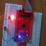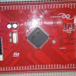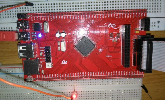
در این پست سورس کار با واحد تایمر میکروکنترلر stm32f407 را برای شما قرار داده ایم. در این برنامه زمان 500میلی ثانیه را با استفاده از تایمر شماره 5 ساخته ایم و سپس در روتین وقفه تایمر پایه ای را به صورت مداوم هر 500 میلی ثانیه یکبار روشن و خاموش می کنیم.میکروکنترلر stm32f407 محصول شرکت st بوده و از فرکانس 168مگاهرتز بهره می برد.این میکروکنترلر دارای حافظه فلش به ظرفیت 1 مگابایت می باشد و در زیر خصوصیات آن آورده شده است.
Key Features
- Core: ARM® 32-bit Cortex® -M4 CPU with FPU, Adaptive real-time accelerator (ART Accelerator™) allowing 0-wait state execution from Flash memory, frequency up to 168 MHz, memory protection unit, 210 DMIPS/1.25 DMIPS/MHz (Dhrystone 2.1), and DSP instructions
- Memories
- Up to 1 Mbyte of Flash memory
- Up to 192+4 Kbytes of SRAM including 64-Kbyte of CCM (core coupled memory) data RAM
- Flexible static memory controller supporting Compact Flash, SRAM, PSRAM, NOR and NAND memories
- LCD parallel interface, 8080/6800 modes
- Clock, reset and supply management
- 1.8 V to 3.6 V application supply and I/Os
- POR, PDR, PVD and BOR
- 4-to-26 MHz crystal oscillator
- Internal 16 MHz factory-trimmed RC (1% accuracy)
- 32 kHz oscillator for RTC with calibration
- Internal 32 kHz RC with calibration
- Sleep, Stop and Standby modes
- VBAT supply for RTC, 20×32 bit backup registers + optional 4 KB backup SRAM
- 3×12-bit, 2.4 MSPS A/D converters: up to 24 channels and 7.2 MSPS in triple interleaved mode
- 2×12-bit D/A converters
- General-purpose DMA: 16-stream DMA controller with FIFOs and burst support
- Up to 17 timers: up to twelve 16-bit and two 32-bit timers up to 168 MHz, each with up to 4 IC/OC/PWM or pulse counter and quadrature (incremental) encoder input
- Debug mode
- Serial wire debug (SWD) & JTAG interfaces
- Cortex-M4 Embedded Trace Macrocell™
- Up to 140 I/O ports with interrupt capability
- Up to 136 fast I/Os up to 84 MHz
- Up to 138 5 V-tolerant I/Os
- Up to 15 communication interfaces
- Up to 3 × I2 C interfaces (SMBus/PMBus)
- Up to 4 USARTs/2 UARTs (10.5 Mbit/s, ISO 7816 interface, LIN, IrDA, modem control)
- Up to 3 SPIs (42 Mbits/s), 2 with muxed full-duplex I2S to achieve audio class accuracy via internal audio PLL or external clock
- 2 × CAN interfaces (2.0B Active)
- SDIO interface
- Advanced connectivity
- USB 2.0 full-speed device/host/OTG controller with on-chip PHY
- USB 2.0 high-speed/full-speed device/host/OTG controller with dedicated DMA, on-chip full-speed PHY and ULPI
- 10/100 Ethernet MAC with dedicated DMA: supports IEEE 1588v2 hardware, MII/RMII
- 8- to 14-bit parallel camera interface up to 54 Mbytes/s
- True random number generator
- CRC calculation unit
- 96-bit unique ID
- RTC: subsecond accuracy, hardware calendar
|
1 2 3 4 5 6 7 8 9 10 11 12 13 14 15 16 17 18 19 20 21 22 23 24 25 26 27 28 29 30 31 32 33 34 35 36 37 38 39 40 41 42 43 44 45 46 47 48 49 50 51 52 53 54 55 56 57 58 59 60 61 62 63 64 65 66 67 68 69 70 71 72 73 74 75 76 77 78 79 80 81 82 83 84 85 86 87 88 89 90 91 92 93 94 95 96 97 98 99 100 101 102 103 104 105 106 |
#include <stm32f4xx.h> volatile char flag=0; volatile uint32_t msTicks; ///////////////////////////////////////////////////////////////////////////// void SysTick_Handler(void) { msTicks++; } ///////////////////////////////////////////////////////////////////////////// void Delay (uint32_t dlyTicks) { uint32_t curTicks; curTicks = msTicks; while ((msTicks - curTicks) < dlyTicks); } ///////////////////////////////////////////////////////////////////////////// int main () { SystemCoreClockUpdate(); if (SysTick_Config(SystemCoreClock / 1000)) { while (1); } #define APB1_clock 84000000 #define freq_timer 10000 RCC->AHB1ENR |= 0x0011; // Enable clock for GPIOE & GPIOA RCC->APB1ENR |= 0x00000008; // Enable Clock for Timer 5 GPIOE->MODER |= 0x00010000; // Output pin for time mark at port E6 TIM5->PSC=(APB1_clock/freq_timer)-1; // freq for timer is 10000 HZ TIM5->ARR = 5000-1; // Auto Reload Register value =>500ms TIM5->DIER |= 0x0001; // DMA/IRQ Enable Register - enable IRQ on update TIM5->CR1 |= 0x0001; // Enable Counting NVIC_EnableIRQ(TIM5_IRQn); // Enable IRQ for TIM5 in NVIC while (1) { } } //////////////////////////////////////////////////////////////////////////////// void TIM5_IRQHandler(void) { if (TIM5->SR & (TIM_SR_UIF)) { if(flag==0){ GPIOE->BSRRL=1«8; flag=1; } else { GPIOE->BSRRH=1«8; flag=0; } TIM5->SR &= ~(TIM_SR_UIF); } } |